A microcontroller (MCU for microcontroller unit) is a small computer on a single metal-oxide-semiconductor (MOS) integrated circuit chip. – Wikipedia: Microcontroller
As a farewell gift for a colleague who is also a fireman 👨🚒, I thought of the following:
- I take a coloring book with a firefighter. In former times Grisu der kleine Drache (Grisu the little dragon) was popular, today it is Sam der Feuerwehrmann (Fireman Sam).
- The book should show a fire truck with blue lights.
- I replace the blue lights with blue LEDs.
- To make it blink, I could use two transistors, NE555 or simply an ATTiny85.
The ATTiny85 is a MCU similar to an Arduino, but a bit smaller, with less IO pins and cheaper. It can be programmed, but not as easy as an Arduino, which you just connect to a computer with a USB cable.
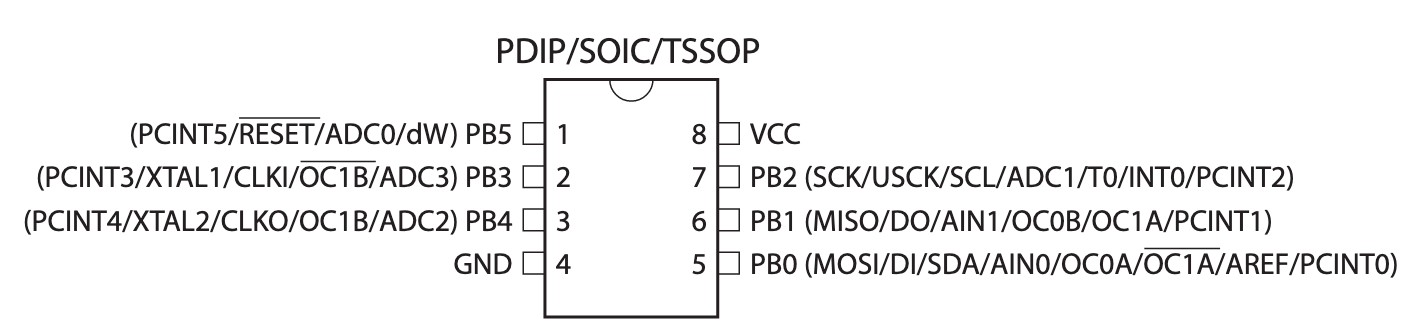
The ATTiny85 has 8 pins in total. Two of them are needed for the power supply. That leaves 4 to 5 pins which I can use as output or input. I only need two pins to connect the LEDs and one pin to switch between different flashing modes. I use two wires as a switch and when you touch both the ATTiny85 reacts. I leave the input pin open and if it is more than 1 second HIGH I switch to the next mode.
Programming ATTiny85
It’s not the first time that I program an ATTiny85 and there are also different guides on the internet: Programming ATtiny85 with Arduino Uno
What is important?
- proper wiring
- Capacitor
- observe the polarity
- do not use it until the Arduino has been programmed as ISP
- the programme
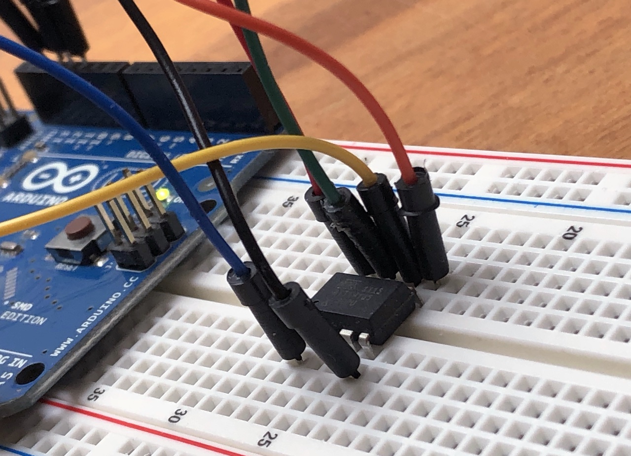
The following picture shows the setup for programming the ATTiny85:
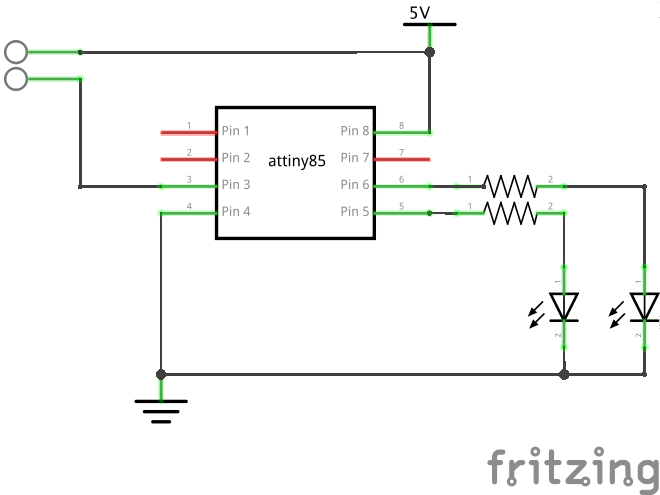
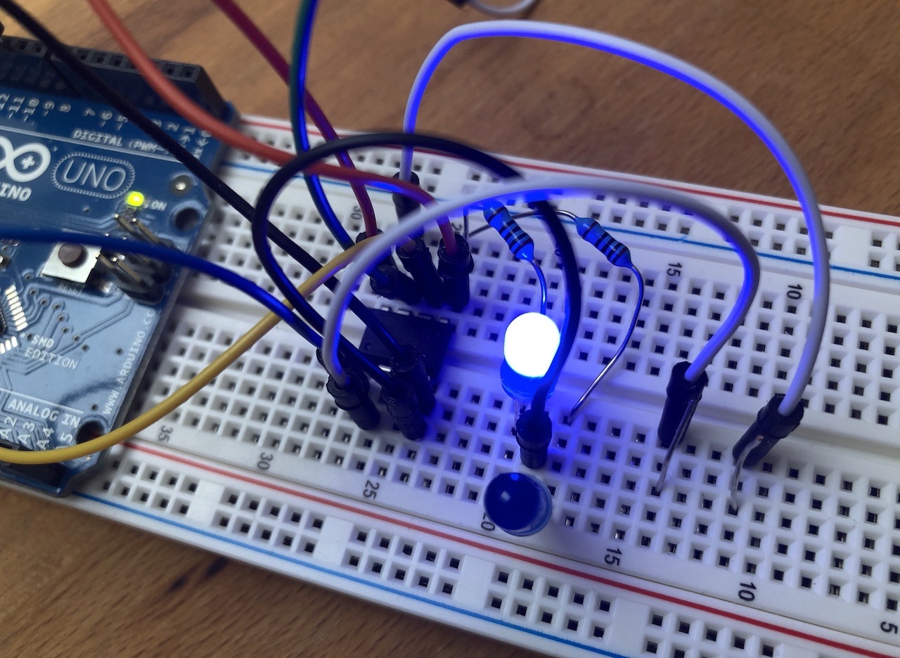
ATTiny85 programmed and wired for blinking:
Flash modes
As you can see in the source code I have the following 5 flashing modes:
- both LEDs blink at the same time
- LEDs flash alternately
- LEDs only light
- LEDs are off
- LEDs flash S.O.S.
Installation
After the ATTiny85 was programmed, I tested it first of course. For this purpose I built the circuit which I also installed in the book.
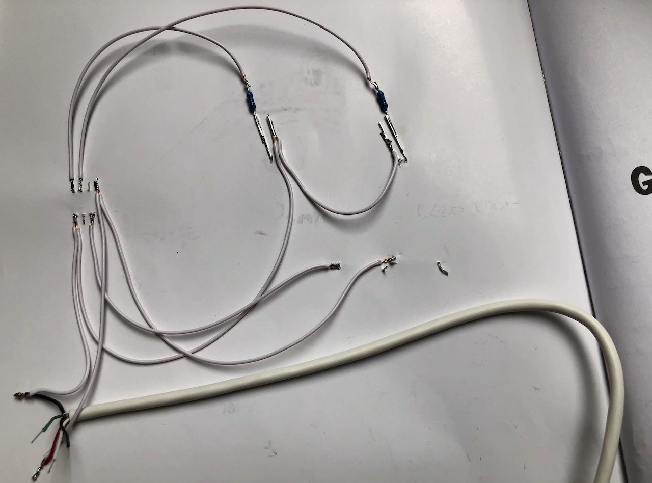
I put the LEDs through the paper and bent the feet, with the ATTiny85 too. Then I soldered everything with the resistor, added the USB cable and tested it. The USB cable is only for power supply. There are also examples to control V-USB with ATtiny45 / ATtiny85 without a crystal. This can be used for example to make the LEDs of the fire engine blink when a tweet with the text “fire” is received.
All electronic parts soldered:
The front of the coloring book with the blue LEDs and ATTiny85:

The mode selector at the wiper:

Summary
A simple gift for less than 10 Euros and something to tinker. And the best thing is that many colleagues have perpetuated themselves in the coloring book.