An FPGA, an AI model, and a simple logic problem — sometimes, the best way to learn is by letting technology teach itself.
I wanted to run a neural network (NN) on an FPGA, and it was my first time working with one. Luckily, I had access to an Anthropic API key, which allowed me to get AI assistance in creating an XOR neural network for an FPGA.
The video shows the setup of an Arduino MKR Vidor 4000 with the blinking LEDs. The two left LEDs represent the input values, and the right LED shows the XOR result.
My First Steps
I had absolutely no experience with FPGAs. Getting the basic “Hello World” LED blinker running was a good start and gave me the confidence to take on a more involved challenge: using an LLM to generate Verilog code for an XOR neural network.
Why XOR?
Setting up an XOR network using a neural network might be overkill. It’s a foundational element in digital logic - something you can easily implement with a few gates. However, it’s a perfect starting point: small, manageable, and with easily predictable outputs.
Using Verilator for Simulation
Compiling code for an FPGA can feel like a black box. That’s where Verilator helps. It converts Verilog code into C++, allowing simulations on a computer before deployment. This step was particularly useful when working with the sigmoid function. Instead of direct calculation, the LLM generated a piecewise linear approximation implemented using LUTs (Look-Up Tables).
Training the Model: From Python to Weight Values
With Python and NumPy, I trained a simple model to obtain the weight and bias values for the XOR neural network. These values were then used in the Verilog code, ensuring the network performed XOR calculations correctly.
Intel Quartus Prime Lite
Intel Quartus Prime is a development suite for FPGA programming. It provides tools for logic synthesis, placement, routing, and simulation. The Lite version, which is freely available, is well-suited for this small project.
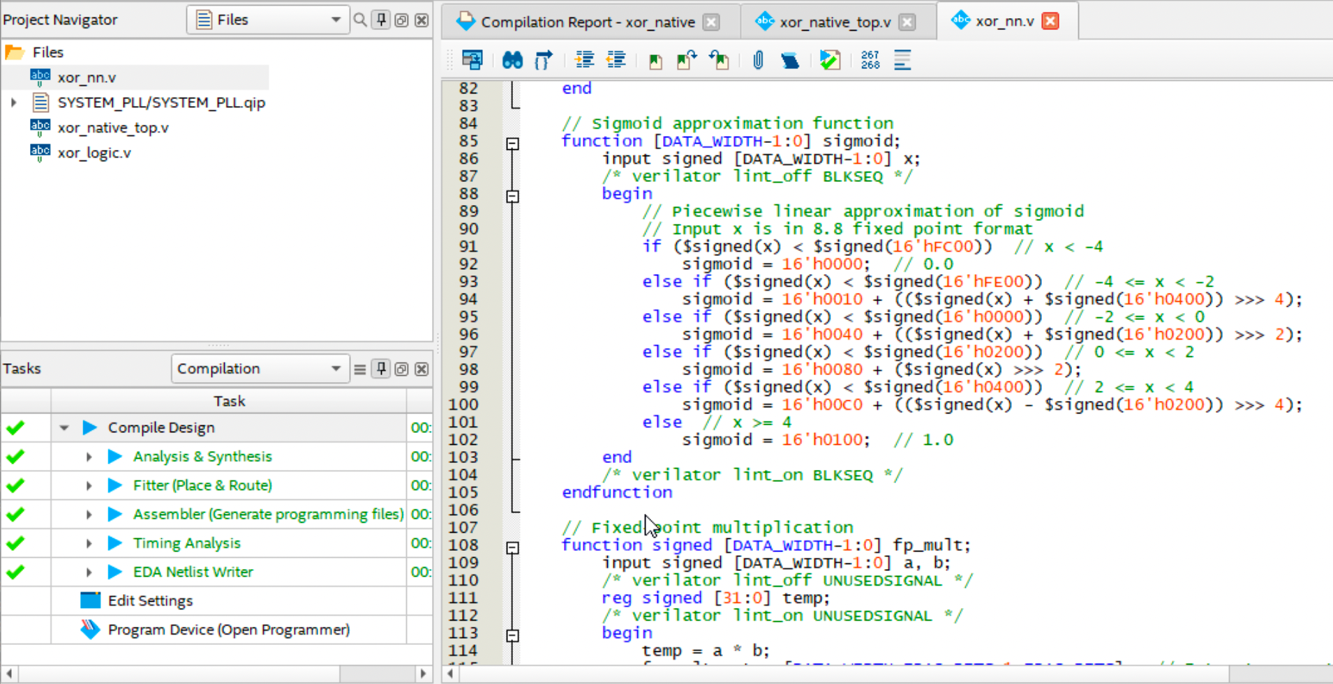 The Quartus screenshot illustrates the sigmoid function. When working with FPGAs, numbers often appear in formats like
 16’h0400, which represents a 16-bit hexadecimal value where the ‘h’ indicates hexadecimal.
State Machine Implementation
The following state machine coordinates operations within the FPGA design, guiding the sequence of computations for the XOR result. It transitions through various states — such as ‘idle,’ ‘compute,’ ‘apply sigmoid,’ and ‘output result’ — ensuring calculations proceed in the correct order.
// State machine
always @(posedge clk or posedge rst) begin
	if (rst) begin
		state <= IDLE;
		done <= 0;
		y_out <= 0;
		acc_idx <= 0;
		mult_result <= 0;  // Initialize this too
	end else begin
		case (state)
			IDLE: begin
				done <= 0;
				acc_idx <= 0;
				if (start) begin
					state <= COMPUTE_HIDDEN;
				end
			end
			COMPUTE_HIDDEN: begin
				// ... computation logic ...
				if (acc_idx == HIDDEN_LAYER_SIZE) begin
				   state <= APPLY_SIGMOID;
				end
			end
			APPLY_SIGMOID: begin
				// ... apply sigmoid function ...
				state <= OUTPUT_RESULT;
			end
			OUTPUT_RESULT: begin
				// ... output result ...
				state <= IDLE;
			end
		endcase
	end
end
MCU and FPGA Working Together
As a final step the SAMD21 microcontroller of the Arduino had to interact with the FPGA. The OUT_Y_PIN acts as an input value, which is set by the FPGA:
// ... setup() function ...
pinMode(INPUT_X1_PIN, OUTPUT);
pinMode(INPUT_X2_PIN, OUTPUT);
pinMode(START_PIN, OUTPUT);
pinMode(OUT_Y_PIN, INPUT);
// Start the computation on the FPGA
digitalWrite(START_PIN, HIGH);
delay(100);
digitalWrite(START_PIN, LOW);

// ... loop() function ...
digitalWrite(INPUT_X1_PIN, inputPattern & 0x01);
digitalWrite(INPUT_X2_PIN, (inputPattern & 0x02) >> 1);
...
int xorResult = digitalRead(OUT_Y_PIN);
Summary
With this small project, I was able to generate my first FPGA process. The LLM created the code for the XOR neural network, simulation, training, and the Arduino integration. It wasn’t perfect at the beginning, but it provided a good starting point. Through more interactions, ‘we’ found a solution.
Simulating the design with Verilator before deployment helps identify and fix potential issues early on. While implementing an XOR network with a neural network might seem like overkill, it serves as an excellent introduction to AI and FPGA programming and might open the door to more advanced applications.
The complete code, including the Verilog implementation and Arduino integration, is available on my GitHub repository: FPGA_XOR_NN.